Hi, welcome back to our Hardcaml MIPS project! Last time, we got our CPU design to run on a real FPGA, and showed the result of a simple program by lighting up LEDs. In this post, we'll refactor our CPU's architecture so that any program can interact with the outside environment by sending/receiving UART packets at will. In addition to letting us output results from a running program instead of hardcoding an "output" phase into our design, this will much more accurately model the architecture of real processors.
At the end, we'll test our processor by using it to run the most underpowered calculator of all time. But more on that later.
Reaching the Outside
When writing software, we often take easy IO for granted. Python's input("Some Message") sends a prompt to user terminals, and makes entered text available to the program. Unix-like device files allow us to control devices through the filesystem. But beneath all the APIs and device drivers, the CPU needs to somehow interact with devices external to it. There are 2 common approaches:
- Memory-Mapped IO (MMIO): each device has an address range in memory. Instead of accessing memory,
lw and sw instructions targeting those addresses are handled by the devices. This is the most common approach.
- Port-Mapped IO (PMIO): each device has a dedicated "port" number. Then, special
in and out (or similarly named) instructions can be used to send/receive data to/from these ports.
Many processors support both. In our project, we'll be implementing memory-mapped IO, since MIPS generally doesn't have in/out. Additionally, MMIO allows us to treat memory as yet another device, which is a convenient abstraction.
A New Architecture
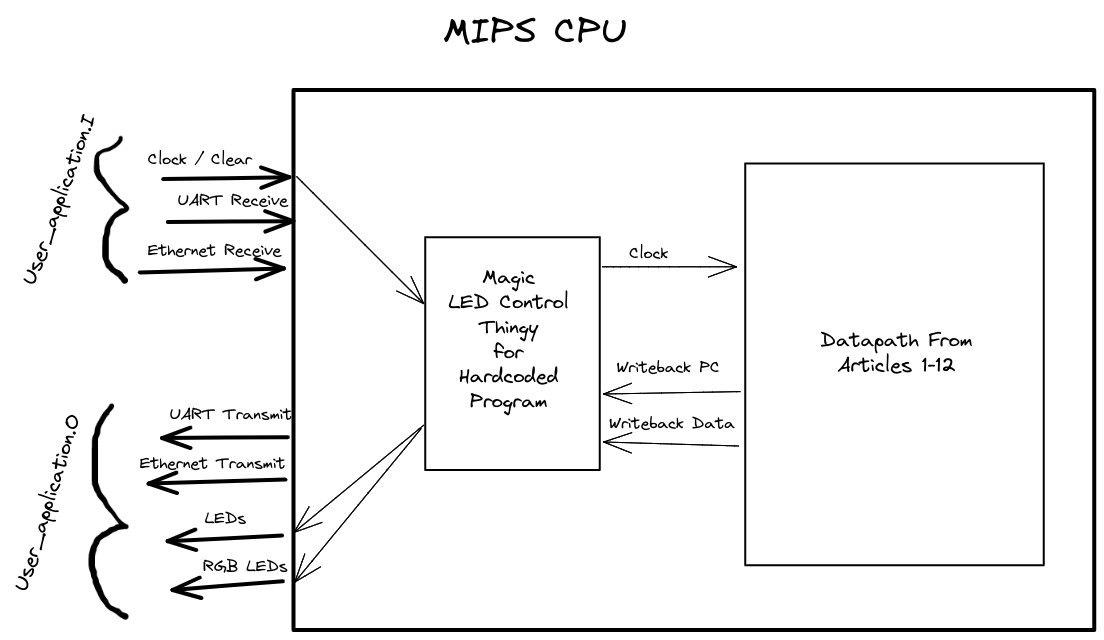
As of the last post, our system architecture looks something like this:

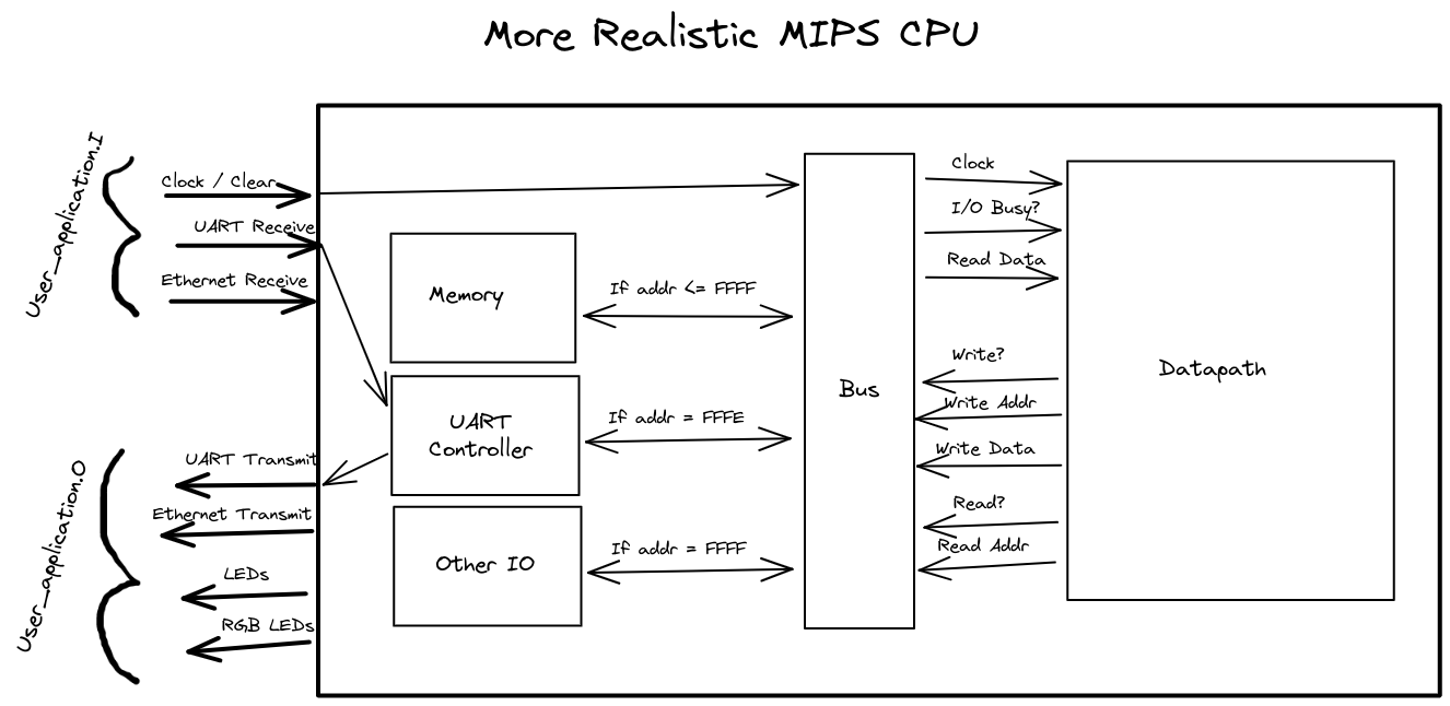
Where the datapath has this design. While this is great for testing that our CPU can run a simple program on a real FPGA, it's not very realistic, and restricted to a single program. If we want to design a feasible processor, IO devices will need to be external to the datapath:

And this is where things really clicked. More types of IO devices (USB ports, VGA/HDMI, PCIe) fit into this scheme easily: just allocate addresses in the memory space. Caching can be implemented in both the datapath side (L1, L2, L3 cache), and in each device. A lot of things are still missing, some of which I'll list in a later section, but this architecture truly resembles an oversimplified CPU.
The UART Protocol
When it comes to communication protocols, UART is as simple as it gets. It uses parallel "receive" (rx) and "transmit" (tx) single-bit-width streams. Data is sent via packets, which have a start bit, ~8 data bits, an optional parity bit, and a stop bit:

Note that the transmissions are value 1 when no data is being sent, and switch to 0 to indicate the start of a packet.
Fortunately, we don't need to worry about encoding/decoding data to/from this particular format, because Hardcaml Arty handles this for us. The interface we deal with for UART rx and tx streams is:
type 'a Byte_with_valid = {
    value : 'a; [@bits 8]
    valid : 'a; [@bits 1]
}
On the receive side, whenever a full packet comes in, there will be a clock cycle where uart_rx.valid is 1, and uart_rt.value is the value of the packet.
For transmission, we set uart_tx.valid to 1, and uart_tx.value to the byte we want to transmit. We just need to make sure that we space out our packets so that Hardcaml_arty has time to transmit each of them. That delay is calculated here.
In the diagram from the previous section, we established that IO devices should take read enable/address and write enable/address/data as input, and output the read data and whether its currently busy (reading or writing). We'll need to build a circuit that provides this interface for UART.
Words in our CPU architecture are 32 bits long, but UART packets have only 8 bits of data. For transmission, we used Hardcaml's Always State Machine API to transmit a CPU word one byte at a time, and only turn off "busy" once all 4 bytes have been sent.
Receipt had the opposite problem: once the CPU requests a read, we need to block until we have received enough packets for a word. This is almost always 4, but since our demo program (a calculator that adds 2 single-digit numbers) required receiving single-byte data, we also terminated words on receipt of the line-end character (\n).
You can see our full UART implementation on GitHub.
There is a simpler way to do all this (only sending/receiving one byte at a time), but we wanted to practice using the state machine API, so we went with the less-practical solution.
Limitations and Hypothetical Improvements
With MMIO and basic UART support implemented, we've decided to conclude this project. However, we still wanted to point out some ways that it could be expanded:
- If we were doing this from scratch, we would make a RISC-V processor instead of a MIPS one. RISC-V is modern, open source, extensible, and well-documented, whereas MIPS is effectively dead outside of introductory classes. Even the MIPS company has switched to RISC-V. It also has great compiler support, which would have saved us from semi-manually translating instructions to hex.
- Our processor is missing some pretty essential features, like support for multiplication/division instructions, traps/interrupts, and privilege levels.
- We haven't implemented support for virtual memory.
- Our instruction memory is still very much hardcoded, and separate from main memory. A real computer still needs a semi-hardcoded bootloader, but after that it should be able to pull instructions from the main memory address space.
- Quite a few optimization features could improve performance, including:
- We haven't implemented support for SIMD or floating point registers/instructions.
- There are a few different decisions we could have made with UART:
- Instead of sending/receiving 4 bytes at a time, we could transmit and receive one byte at a time. This would be simpler, more general, and wouldn't require arbitrary word terminations, but we wanted to try building more complicated Hardcaml state machines.
- Instead of synchronously blocking until bytes are sent/received, we could output "busy" and "has data" at other addresses, and have the running program poll UART. Alternatively, if we had implemented interrupts, we could use that to notify the running program about incoming data.
- The receive buffer could be turned into a circular buffer, which could hold more than one word at a time. The CPU would then be able to write to a mapped address, which would clear this buffer on demand.
Project Conclusion v2
We decided to test our new architecture and UART support by running the most underpowered calculator of all time. Users can send it 2 single-digit numbers, it will add them, and send the result back (as long as it doesn't exceed 10). And indeed:
As far as programs go, this is far from impressive. But its enough to demonstrate that our architecture could easily support a more... usable program. In fact, if we were to implement just several of the features listed in "Hypothetical Improvements", the processor could run an entire operating system.
Before college, the inner workings of computers always seemed mysterious and unapproachable. Even after designing the first version of this CPU for class, it was hard to fully bridge the worlds of hardware and software. But after this project, where we used our design to execute a simple program that interacted with both memory and an external computer, everything clicked.
Once again, we'd like to thank Andy Ray, Fu Yong Quah, Ben Devlin, Yaron Minsky, and the rest of the Jane Street hardware engineering team for building these awesome tools, making them freely available, helping us understand them, and then sending us actual FPGAs to try them on real hardware. It's been a very fun and enriching challenge.
We also hope that these blog posts have been useful and enjoyable if you're looking to use Hardcaml in a project. If you have any questions or comments, we'd love to hear from you!